
background
The theory of corresponding points has been developed to account for how the visual system recovers a single percept from two different retinal images of the same visual scene. For every retinal point in the left eye (aL, eL), there is a retinal point in the right eye (aR, eR) that, when stimulated, gives rise to the same perceived direction. These pairs of points are corresponding points. From the retinal coordinates of corresponding points, a model of the eyes’ optics and a known fixation position, we can calculate object locations that stimulate corresponding points. Objects at these locations must be seen as single because each eye reports the same direction. These locations define the horopter. It is useful to know where the horopter is because this is where fusion is easiest, stereoacuity is highest, and depth discrimination is best (Ogle, 1953; Blakemore, 1970; Krekling, 1974; Westheimer & McKee, 1978). If corresponding points are in fixed positions on the retinas, it is straight-forward to predict these locations for any fixation position. The intersections of rays traced from corresponding retinal-image points out into the external scene would define the horopter for any fixation position. Unfortunately, there are numerous reports that corresponding points are not fixed retinally. Clark (1936), Amigo (1965), Flom and Eskridge (1968), Shipley and Rawlings (1970b), Remole (1985), Robertson and Schor (1986), Kertesz and Lee (1987), and Fogt and Jones (1998a, 1998b) all concluded that corresponding points shift with horizontal vergence. We have re-examined whether corresponding retinal points shift with eye movements.
The figures below illustrate two hypotheses of how and why corresponding points shift with changes in vergence.
Local Shift Hypothesis
The left figure shows the local shift hypothesis. Small errors in binocular fixation are typical (especially for very near or very far fixation points). Corresponding points might shift locally near the fovea to compensate for these small errors. The predictions of this hypothesis can be seen by moving the fixation point in and out. The thick solid line represents the predicted shape of the horopter with corresponding points near the fovea shifting to compensate for fixation error. The dashed line at fixation represents the shape of the horopter for a fixed set of corresponding points near the foveas.
Flattening Hypothesis
The figure to the left shows the flattening hypothesis. Some horopter measurements show it to be flatter at all distances than is predicted by a fixed set of corresponding points. This would give viewers an advantage for fusing flat surfaces at all viewing distances than a fixed corresponding points. In the figure to the left, the solid black curved line depicts the horopter for a fixed set of corresponding points. The solid blue line represents a flat horopter for all veiwing distances.The disparity values at the bottom of the figure show the disparity of a point, P1_flat, on a flat horopter changes with viewing distance.You can see this by moving the red fixation point toward and away from the eyes. This change in disparity means that the retinal coordinates of corresponding points shift such that their visual lines always intersect on a flat surface.
ocular changes with viewing distance and horopter measurement error
The goal of this study is to be to compare horopter measurements taken at different viewing distances. Here we will consider several factors that can cause apparent changes in the horopter with viewing distance even when corresponding points are fixed.
Fixation errors. When measuring the horopter, it is critically important to know where the observer is looking. We were concerned with two types of fixation errors: transient and sustained. Transient fixation errors occur when observers move their eyes during measurement of a point on the horopter. These errors are likely to occur with method of adjustment where observers are asked to maintain central fixation while making judgments in the periphery. Sustained fixation errors refer to the observers tendency to look, on average, in front of or behind the attempted fixation point.
Optical changes with vergence. The correct vertex of left eye and right eye anglesbetween fixation and corresponding horopter points is the nodal point of the appropriate eye. Unfortunately the exocentric positions of the nodal points shift with vergence. This is because the nodal points are located in front (closer to the cornea) of the center of rotation of the eyes and because of accommodative-vergence. The figure below illustrates the error when a fixed nodal point is used to measure disparity between corresponding points. In this illustration, NP=nodal point, CR=center of rotation, F=fovea, LE=left eye, RE=right eye, CP=corresponding point. In this figure, CP(1LE) and CP(1RE) are a pair of retinal corresponding points that are fixed in retinal coordinates. Visual lines projected out from these points intersect on the horopter at Horopter P(1). By moving the fixation point in and out you can see how the measured disparity depends on the choice of vertex. If fixed points at the front of the corneas are used as the verticies for left and right eye angles, disparity decreases as veiwing distance increases. If fixed points at the centers of rotation are used as the verticies for left and right eye angles, disparity increases as veiwind distance increases. Only when the nodal points of the eyes are used as verticies do corresponding points appear retinally fixed.
eliminating horopter measurment error
Fixation errors. Transient fixation errors were eliminated by flashing Nonius targets for 175ms. There were 19 possible position between -6 and 6 deg. Observers reported the apparent misalignment (top line lest or right) of the Nonius lines with a keypress. Staircases were used to find the point of subjective alignment.. Sustained fixation errors were measured by subjective Nonius technique throughout the experiment (i.e. one of the 19 possible positions was at fixation).
Optical changes with vergence. As stated in the previous page, a problem with measuring the disparity between horopter points as a function of veiwing distance is that the nodal points of the eyes move in exocentric coordinates. Rather than attempt to track the positions of the nodal points, we used a specially designed haploscope with image planes that move with the nodal points. This haploscope is depicted below. As can be see by moving the virtual fixation point, the nodal points [NP(L) and NP(R)] of the eyes move with the image planes of the haploscope. So, optical projections from the haploscope image planes do not change with vergence. We can therefore measure angles between corresponding points from nodal points that are in fixed positions relative to the haploscope image planes.
Accomodative-Vergence. This term refers to accommodation that occurs as the eyes verge. Becasue the image planes of the haploscope were at a fixed distance (39cm) from the eyes and we simulated veiwing distances of 19 and 172cm, accommodative vergence would cause blurring of the images. To insure that retinal image properties were fixed across veiwing distances, pinhole pupils were placed on the corneas using contact lenses.
methods, results and discussion
Methods. Nonius targets were flashed for 175ms in one randomly selected position. There were 19 possible position between -6 and 6 deg. Observers reported the apparent misalignment (top line lest or right) of the Nonius lines with a keypress. Staircases were used to find the point of subjective alignment.
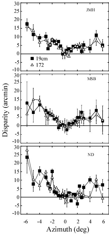
Results. The adjacent figure shows results for three observers. Horopter settings were adjusted for fixation disparity. To adjust for fixation disparity, the functions have been shifted vertically such that the point at azimuth = 0 has a disparity of 0 deg. The required shifts were -10.7 and 0.8 arcmin for observer JMH at 19 and 172 cm, -10.9 and 8.1 for ND, and -9.1 and 3.5 for MSB. Error bars represent +/-1 SD of the last 6 reversals in each staircase (each point represents the results of two independent staircases observers JMH and MSB and only one staircase for ND) . The adjusted disparity of the horopter settings are plotted as a function of azimuth. The filled and unfilled symbols represent data collected at veiwing distances of 19 and 172 cm, respectively.
Flattening Hypothesis. If corresponding points changed on the retina as a function of fixation distance (as suggested by the flattening hypothesis), the overall shape of the curves would change with viewing distance. There is no obvious shape change so these data also offer no support for the flattening hypothesis.
Local Shift Hypothesis.The local shift hypothesis predicts that disparity should increase from an azimuth of 0-1.5 deg more rapidly at 19 than at 172 cm. No such change was observed, so these data offer no support for the local shift hypothesis.
Conclusions. Corresponding points are in fixed retinal locations and do not shift with viewing distance.