background
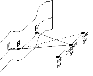
The graphic below depicts a binocularly fixated surface. Vectors B, M, and F represent the positions of points B, M, and F relative to the observer. Recovery of the 3-dimensional positions of those points requires an estimation of the lengths and directions of B, M, and F. Most research in binocular vision has concerned estimation of the lengths, but the directions must also be estimated in order to recover the positions of the surface points. We've been investigating how visual direction is esimated in binocular and monocular viewing situations.

hering's laws of visual direction
The method for estimating directions in binocular viewing was described by Hering (1879) and elaborated by Ono and Mapp (1995), Banks et al (1997), and others. Hering's Laws can be summarized by 3 calculations. 1) The eyes' version is estimated; this is the average of the left and right eyes' rotations (aL & aR) when fixating the point F. (The angle values in the lower right are expressed in radians.) 2) Oculocentric directions are calculated; these are the retinal angles between the visual axes (lines of sight) and visual lines to the object (B or M). 3) Headcentric directions are given by the oculocentric directions plus the version. These calculations are depicted in the sketch below. The fixation point is represented by the dot F; you can vary its position by dragging the dot. An object visible to both eyes is represented by B; vary position by dragging the dot. An object visible to the left eye only is represented by M; vary its position by dragging. The sketch shows the perceived directions of B and M according to Hering's Laws. The directions are represented by the thick lines; green lines represent the directions reported by the left eye and red lines directions reported by the right eye. Notice that the origin of the direction vectors is the cyclopean eye: Directions are perceived as if we viewed objects from a point between the two eyes. When B is on the Vieth-Muller Circle, the directions reported by the two eyes are the same. When B is slightly nearer or farther than the Circle, the directions are slightly different, but the fusion capacity of the visual system yields a single perceived direction; that single direction is the average of the two directions shown. Now place B inside the Vieth-Muller Circle and then place M in the same position as B. The average of the directions for B (the fused direction; this direction isn't shown but would bisect the between two vectors) is different from the direction for M. Thus, Hering's Laws predict different perceived directions for binocular and monocular objects in the same position in space.
perceived direction near an occluder
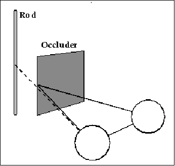
Because Hering's Laws predict different perceived directions for binocular and monocular objects in the same position in space, they predict that a rod partially behind an occluder will be seen in two directions, different ones for the monocular and binocular parts of the rod.

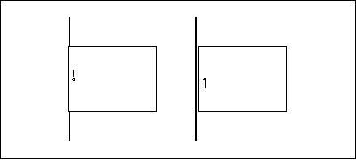
The figure below is a stereogram depicting the partial occlusion situation schematized in the previous page. Cross-fuse the image by directing your left eye toward the small vertical lines in the right part of the figure and by directing your right eye toward the vertical lines in the left part. You should see three parts when you've fused it correctly; we're interested in the middle one. Fixate the small vertical lines such that they appear vertically aligned. Once you have it, notice the apparent shape of the long vertical line: Its middle appears to bow leftward, an observation that is consistent with Hering's Laws of visual direction. The bow is smooth; Hering's Laws predict a discontinuity (a sharp leftward displacement), so the smoothness of the bowed image is inconsistent with Hering's Laws. We have examined this effect and the rules that govern the assignment of visual direction in a recent paper (van Ee, R, Banks, MS, & Backus, BT. Perceived visual direction near an occluder, Vision Research, in press).


